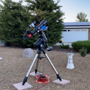
To use, install Scilab 6.0.2 or later, put both .sce files in the same directory and double-click on obsy.sce. Scilab is very similar to Matlab and is free. I am not aware of any bugs but don't take my word for it; I don't take responsibility. If you want to try it and need help just shoot me a PM. The script has my South Side obsy, a converted 6x8 lean-to shed, as an example.
FWIW, who knows.
File: obsy.sce
Code: Select all
// Observatory simulation program.  The simulation shows the
// telescope rotating over a grid of angles in HA (Hour Angle)
// and DEC (Declination) and produces a clearance map of the OTA
// relative to the observatory walls.  It is intended for
// roll-off / slide-off observatories that are made of qualdrilateral
// panels.  It produces 2 results:
// 1) A 3D visual animation in a plot window.  You can rotate the
//    viewing angle using right-click and move.  This animation
//    shows how well the telescope fits inside the observatory
//    walls and how far it sticks out above for any position.
// 2) An analysis of minimum clear view altitude over the wall.
//    It consists of a clearance map that shows the fraction
//    of clearance relative to the area of the objective (lens
//    or mirror), and a 3D plot of minimum clearance in the
//    same 3D configuration as the visual animation.
// In Scilab (6.0.2 and later), start Scilab by doubl-clicking
// the obsy.sce file icon.  This will start Scilab in the
// directory of that file.  Then press F5 to start the simulation.

exec("lib.sce");
i2m = 0.0254;
f2m = 12*i2m;

// Example for a rectangular observatory floor plan where
// the X coordinate runs from 0 to xWidth, and the Y coordinate
// runs from 0 to yWidth.  Two wall heights are used as in the
// case of a "lean-to" shed.
xWidth = 8*f2m;         // Width in X direction
yWidth = 6*f2m;         // Width in Y direction
sWall = 5.5*f2m;        // Wall height for Y = 0
nWall = 80*i2m;         // Wall height for Y = yWidth
x0 = 1.30;              // Tripod center X coordinate
y0 = 1.10;              // Tripod center Y coordinate
theta = -atan(84/180);  // Angle between SN line and Y axis
                        // Negative = clockwise looking down

lat = 34*%pi/180;       // Latitude of observatory
lleg = 0.83;            // Leg length
zleg = 0.75;            // Leg height (for a pier: set equal to lleg)
rleg = 0.05;            // Leg radius
pier = 0.30;            // Pier height (top of legs to Alt axis)
lra = 0.09;             // RA axis length
ldec = 0.20;            // DEC axis length (center of RA axis to OTA tube)

// Enter your OTA configuration.  The code below offers a choice
// of two; for just one, get rid of the if/then/else statement.
// 1) To simulate the field of view clearance, add the mirror
//    clearance inside the OTA to ldec, and set rota to the
//    mirror radius.
// 2) To simulate the OTA tube clearance to the walls, set rota
//    to the OTA radius, and leave ldec as is.
// This choice probably only matters if the fit is tight.
if %f then
    // MN152 Mak-Newt
    rota = 3*i2m;           // OTA radius in m
    lota = 0.83;            // OTA length in m
    cgOta = 0.42;           // OTA center of gravity in m
    ldec = ldec + i2m/2;    // Mirror clearance inside OTA
else
    // GSO 12" Newtonian
    rota = 6*i2m;           // OTA radius in m
    lota = 1.17;            // OTA length in m
    cgOta = 0.44;           // OTA center of gravity in m
    ldec = ldec + i2m;      // Mirror clearance inside OTA
    zleg = zleg*1.3;        // Leg height
    lleg = lleg*1.3;        // Leg length
    y0 = 2.75*f2m;          // Can fit the Newt at 20 degrees min Alt
end

g11 = [x0; y0; zleg + pier; theta];     // Mount [x; y; pier top height; N/S angle offset]
altMin = 20*%pi/180;    // Minimum altitude
haDegs = [-90:1:90];    // HA angles (2nd number is resolution)
decDegs = [-180:1:180]; // DEC angles (2nd number is resolution)
// Advice:  Set the resolution to 4 when you are trying things out
// because it is 16 times faster than 1 albeit with less resolution.

function [px, py, pz, x, y, z] = obsyClosed()
    // Return the observatory panel coordinates. Each column of
    // the array represents a quadrilateral panel in the format
    // [x1;x2;x3;x4;x5], [y1;y2;y3;y4;y5], [z1;z2;z3;z4;z5],
    // where (x1,y1,z1) are the vertices.  Note that
    // x1=x5, y1=y5, z1=z5 must hold for each panel.
    x = [0; xWidth];
    y = [0; yWidth];
    z = [0; sWall; nWall];
    ix = [1,2,2,1,1; 2,2,2,2,2; 2,1,1,2,2; 1,1,1,1,1];
    iy = [1,1,1,1,1; 1,2,2,1,1; 2,2,2,2,2; 2,1,1,2,2];
    iz = [1,1,2,2,1; 1,1,3,2,1; 1,1,3,3,1; 1,1,2,3,1];
    px = zeros(5,4);
    py = zeros(5,4);
    pz = zeros(5,4);
    for i = 1:4 do
        px(:,i) = x(ix(i,:));
        py(:,i) = y(iy(i,:));
        pz(:,i) = z(iz(i,:));
    end
endfunction

function [px, py, pz] = obsyOpen()
    // After the simulation the observatory is plotted using
    // this function.  It can be different from obsyClosed if
    // the observatory can open up during operation.
    // If not, it will be the same as obsyClosed.
    [px, py, pz, x, y, z] = obsyClosed();
endfunction

// Array of viewing angles.  If you want to just view it from
// the top,
angles = [0,-90; 90,90; 90,0];  // From Z, X and Y axes
angles = [0,-90];               // From Z axis only
nAngles = size(angles, 1);
nRa = length(haDegs);
nDec = length(decDegs);
frac = zeros(nRa, nDec);
alt = zeros(nRa, nDec);
x = zeros(nRa, nDec);
y = zeros(nRa, nDec);
observatory = obsyOpen;
for iAngle = 1:nAngles do
    ra = 0;
    dec = %pi/2;
    // Plot the observatory panels
    [xobs, yobs, zobs] = observatory();
    fig1 = scf(0); clf();
    plot3d(xobs, yobs, zobs);
    // Plot the legs
    [xl, yl, zl] = legs(g11, rleg, zleg, lleg);
    plot3d(xl, yl, zl);
    // Plot the pier
    [xb, yb, zb] = cylinder(0.05, pier, 10);
    plot3d(xb+g11(1), yb+g11(2), zb+zleg);
    // Plot the RA axis
    [xra, yra, zra, decBase] = raAxis(g11, lra, lat);
    plot3d(xra, yra, zra);
    // Plot the DEC axis
    [xdec, ydec, zdec, otaBase] = decAxis(g11, lra, ldec, lat, ra, decBase);
    plot3d(xdec, ydec, zdec);
    // Plot the OTA
    [xo, yo, zo] = ota(g11, rota, lota, lat, ra, dec, lra, ldec, cgOta, otaBase);
    plot3d(xo, yo, zo);

    // Set the plot boundaries and viewing angle
    xMin = min(xobs-f2m); xMax = max(xobs+f2m);
    yMin = min(yobs-f2m); yMax = max(yobs+f2m);
    zMin = min(zobs); zMax = max(zobs+f2m);
    fig1.children(1).data_bounds = [xMin,yMin,zMin;xMax,yMax,zMax];
    fig1.children(1).isoview = "on";
    fig1.children(1).rotation_angles = angles(iAngle,:);

    c = fig1.children(1).children(1);
    b = fig1.children(1).children(2);
    iRa = 0;
    for haDeg = haDegs do
        iRa = iRa + 1;
        ra = haDeg*%pi/180;
        [xdec, ydec, zdec, otaBase] = moveRa(b, g11, lra, ldec, lat, ra, decBase);
        iDec = 0;
        for decDeg = decDegs do
            iDec = iDec + 1;
            dec = decDeg*%pi/180;
            [xo, yo, zo] = moveDec(c, g11, rota, lota, lat, ra, dec, ...
                lra, ldec, cgOta, otaBase, altMin);
            // Center line p1 to p2
            p1 = [mean(xo(1,:)); mean(yo(1,:)); mean(zo(1,:))];
            p2 = [mean(xo(4,:)); mean(yo(4,:)); mean(zo(4,:))];
            [frac1, xx, yy, alt1] = clearance(p1, p2, xobs, yobs, zobs, rota);
            frac(iRa, iDec) = frac1;
            x(iRa, iDec) = xx;
            y(iRa, iDec) = yy;
            alt(iRa, iDec) = alt1;
        end
    end
end

// Scan the clearance map for the bump up
ndx1 = find((frac(:,2:$) == 1) & (frac(:,1:$-1) < 1));
if ndx1 <> [] then
    ndx1 = ndx1 + length(haDegs);
end
// Scan the clearance map for the bump down
ndx2 = find((frac(:,2:$) < 1) & (frac(:,1:$-1) == 1));
ndx = [ndx1, ndx2];
// Plot it
fig2 = scf(2); clf();
// Plot the observatory panels
[xobs, yobs, zobs] = observatory();
plot3d(xobs, yobs, min(zobs, max(alt(ndx)))*180/%pi);
zlabel("Alt");
if ndx <> [] then
    // Plot the 100% clearance altitude markers
    param3d(x(ndx), y(ndx), alt(ndx)*180/%pi);
    fig2.children(1).children(1).line_mode = "off";
    fig2.children(1).children(1).mark_size = 1;
    fig2.children(1).children(1).mark_mode = "on";
    fig2.children(1).children(1).mark_style = 0;
    fig2.children(1).children(1).mark_style = 0;
    zMax = max(alt(ndx)*180/%pi);
    fig2.children(1).data_bounds = [xMin,yMin,0;xMax,yMax,zMax*1.2];
end

// Surface plot of clearance fraction in function of RA and DEC
fig3 = scf(1); clf();
surf(decDegs', haDegs', frac);
xlabel("DEC (degrees)");
ylabel("HA (degrees)");
zlabel("Clearance");

// Final/preferred position, closed or open
showOpen = %t
if showOpen then
    ra = 0;
    dec = 0;
    observatory = obsyOpen;
else
    ra = -%pi/2;
    dec = %pi/2+lat;
    observatory = obsyClosed;
end
[xdec, ydec, zdec, otaBase] = moveRa(b, g11, lra, ldec, lat, ra, decBase);
[xo, yo, zo] = moveDec(c, g11, rota, lota, lat, ra, dec, ...
    lra, ldec, cgOta, otaBase, -%pi/2);
[xobs, yobs, zobs] = observatory();
d = fig1.children(1).children(6).data;
d.x = xobs; d.y = yobs; d.z = zobs;
fig1.children(1).children(6).data = d;
Code: Select all
function [x, y, z] = cylinder(r, h, n)
    // Cylinder panels centered around [0;0;h/2]
    phi = 2*%pi/n;
    x = zeros(n, 5);
    y = zeros(n, 5);
    z = zeros(n, 5);
    for i = 1:n do
        x1 = r*cos((i-1)*phi);
        x2 = r*cos(i*phi);
        y1 = r*sin((i-1)*phi);
        y2 = r*sin(i*phi);
        x(i, :) = [x1, x2, x2, x1, x1];
        y(i, :) = [y1, y2, y2, y1, y1];
        z(i, :) = [0, 0, h, h, 0];
    end
    x = x';
    y = y';
    z = z';
endfunction

function [x, y, z] = givens(off, axis, phi, x, y, z)
    // Perform a Givens rotation centered around an offset
    [m, n] = size(x);
    x = x - off(1);
    y = y - off(2);
    z = z - off(3);
    c = cos(phi);
    s = sin(phi);
    axis = axis/norm(axis);
    [u, sv, v] = svd(axis);
    p = [x(:), y(:), z(:)]';
    p1 = u(:, 2:3)'*p;
    p1 = u(:, 2:3)*[c*p1(1,:) - s*p1(2,:); s*p1(1,:) + c*p1(2,:)];
    p2 = u(:,1)*(u(:, 1)'*p);
    p = p1 + p2;
    x = matrix(p(1,:), m, n) + off(1);
    y = matrix(p(2,:), m, n) + off(2);
    z = matrix(p(3,:), m, n) + off(3);
endfunction

function [xo, yo, zo] = ota(g11, rota, lota, lat, ra, dec, ...
            lra, ldec, cgOta, otaBase)
    [xo, yo ,zo] = cylinder(rota, lota, 20);
    zo = zo - cgOta;
    yo = yo - rota;
    c = cos(lat);
    s = sin(lat);
    [xo, yo, zo] = givens(zeros(3,1), [1;0;0], lat-%pi/2, xo, yo, zo);
    raRot = [0; c; s];
    decRot0 = [0; -s; c];
    [xo, yo, zo] = givens(zeros(3,1), decRot0, dec, xo, yo, zo);
    [xo, yo, zo] = givens(zeros(3,1), raRot, ra, xo, yo, zo);
    theta = g11(4);
    [xo, yo, zo] = givens(zeros(3,1), [0;0;1], theta, xo, yo, zo);
    xo = xo + otaBase(1);
    yo = yo + otaBase(2);
    zo = zo + otaBase(3);
endfunction

function [xl, yl, zl] = legs(g11, rl, zleg, lleg)
    phi = acos(zleg/lleg);
    theta = g11(4);
    [x, y, z] = cylinder(rl, lleg, 10);
    [x, y, z] = givens(zeros(3,1), [1;0;0], phi, x, y, z);
    y = y + lleg*sin(phi);
    xl = x; yl = y; zl = z;
    [x, y, z] = givens(zeros(3,1), [0;0;1], 2*%pi/3, x, y, z);
    xl = [xl,x]; yl = [yl,y]; zl = [zl, z];
    [x, y, z] = givens(zeros(3,1), [0;0;1], 2*%pi/3, x, y, z);
    xl = [xl,x]; yl = [yl,y]; zl = [zl, z];
    [xl, yl, zl] = givens(zeros(3,1), [0;0;1], theta, xl, yl, zl);
    xl = xl + g11(1);
    yl = yl + g11(2);
endfunction

function [x, y, z, decBase] = raAxis(g11, lra, lat)
    theta = g11(4);
    [x, y, z] = cylinder(0.05, lra, 10);
    [x, y, z] = givens(zeros(3,1), [1;0;0], lat-%pi/2, x, y, z);
    [x, y, z] = givens(zeros(3,1), [0;0;1], theta, x, y, z);
    x = x + g11(1);
    y = y + g11(2);
    z = z + g11(3);
    decBase = [mean(x(4,:)), mean(y(4,:)), mean(z(4,:))];
endfunction

function [x, y, z, otaBase] = decAxis(g11, lra, ldec, lat, ra, decBase)
    theta = g11(4);
    [x, y, z] = cylinder(0.05, ldec, 10);
    [x, y, z] = givens(zeros(3,1), [1;0;0], lat, x, y, z);
    c = cos(lat);
    s = sin(lat);
    raRot = [0; c; s];
    [x, y, z] = givens(zeros(3,1), raRot, ra, x, y, z);
    [x, y, z] = givens(zeros(3,1), [0;0;1], theta, x, y, z);
    x = x + decBase(1);
    y = y + decBase(2);
    z = z + decBase(3);
    otaBase = [mean(x(4,:)), mean(y(4,:)), mean(z(4,:))];
endfunction

function [xdec, ydec, zdec, otaBase] = moveRa(b, g11, lra, ldec, lat, ra, decBase)
    [xdec, ydec, zdec, otaBase] = decAxis(g11, lra, ldec, lat, ra, decBase);
    d = b.data;
    d.x = xdec;
    d.y = ydec;
    d.z = zdec;
    b.data = d;
endfunction

function [xo, yo, zo] = moveDec(c, g11, rota, lota, lat, ra, dec, ...
            lra, ldec, cgOta, decBase, altMin)
    [xo, yo, zo] = ota(g11, rota, lota, lat, ra, dec, lra, ldec, cgOta, decBase);
    lim = lota*sin(altMin);
    if zo(4,1) < zo(1,1) + lim then
        return;
    end;
    d = c.data;
    d.x = xo;
    d.y = yo;
    d.z = zo;
    c.data = d;
endfunction

function [ok, a, b, c, d, xx, yy] = closestEdgeDistance(p1, p2, q1, q2, r, tol)
    dp = p2 - p1;
    dq = q2 - q1;
    ok = %f; a = 0; b = 0; c = 0; d = 0; xx = 0; yy = 0;

    // Project p1 + a*dp on the edge
    // Calculate the intersection of the ground projection
    // p1+a*dp = q1+b*dq
    X = [dp(1:2), -dq(1:2)];
    Y = (q1(1:2) - p1(1:2));
    theta = X\Y;
    a = theta(1);
    b = theta(2);
    if norm(Y - X*theta) > tol then
        return;
    end
    if (b < -tol) | (b > 1+tol) | (a < -tol) then
        return;
    end
    xy = p1(1:2) + a*dp(1:2);
    xx = xy(1);
    yy = xy(2);

    // Use an SVD to determine the perpendicular of [dp,dq]
    [u, s, v] = svd([dp, dq]);
    perp = u(:, 3); // Unit vector perpendicular to dp and dq
    // p1+a*dp = q1+b*dq + c*perp
    if [0,0,1]*perp < 0 then
        perp = -perp;   // The OTA points over iff c > 0
    end
    X = [dp, -dq, -perp];
    Y = q1 - p1;
    theta = X\Y;
    if (norm(Y - X*theta) > tol) then
        return;
    end

    ok = %t;
    a = theta(1);
    b = theta(2);
    c = theta(3);
    d = abs(c); // Distance between centerline and edge
endfunction

function frac = chordArea(d, r)
    // r = circle radius
    // d = cut position relative to the center (positive = above)
    // frac = chord area fraction relative to the circle area
    // https://en.wikipedia.org/wiki/Circular_segment
    if d >= r then
        frac = 0;
        return;
    end
    if d <= -r then
        frac = 1;
        return;
    end
    if d > 0 then
        theta = 2*acos(d/r);
        a = (r*r/2)*(theta - sin(theta));
        frac = a/(%pi*r*r);
    else
        // Chord calculation for the other side
        theta = 2*acos(-d/r);
        a = (r*r/2)*(theta - sin(theta));
        frac = 1 - a/(%pi*r*r);
    end
endfunction

function [fracBest, xxBest, yyBest, altBest] = clearance(p1, p2, xobs, yobs, zobs, rota)
    // Scope centerline runs from p1 to p2 in 3D
    // xyzobs are the observatory panels
    // rota is the OTA radius
    xy = [0;0];
    zmin = min(zobs);
    tol = 1e-10;
    [m, n] = size(xobs);    // n = number of edges of all panels
    dBest = 1e10;
    alt = 0;        // Default value, should not happen
    fracBest = 1;   // 100% obscured
    dp = p2 - p1;
    xxBest = 0;
    yyBest = 0;
    altBest = 0;
    fracBest = 0;

    // Bail out if we're pointing straight up or down
    if norm(dp(1:2)) < tol then
        if dp(3) > 0 then
            fracBest = 1;
        end
        return;
    end

    // Bail out if we're pointing down
    if dp(3) <= 0 then
        return;
    end

    for i = 1:n do
        for j = 1:4 do
            if (zobs(j,i) == zmin) | (zobs(j+1,i) == zmin)
                // Ground or vertical edge, skip it
                continue;
            end
            q1 = [xobs(j  ,i); yobs(j  ,i); zobs(j  ,i)];
            q2 = [xobs(j+1,i); yobs(j+1,i); zobs(j+1,i)];
            dq = q2 - q1;
            [ok, a, b, c, d, xx, yy] = closestEdgeDistance(p1, p2, q1, q2, rota, tol);
            if ~ok then
                continue;   // Not the edge the OTA is pointing at
            end
            if d >= dBest then
                continue;   // Some other edge was closer
            end
            if d >= rota then
                // OTA either looks over or under, 100%
                if c > 0 then
                    frac = 1;
                else
                    frac = 0;
                end
            else
                // c = position of center relative to the edge (positive = above)
                frac = chordArea(-c, rota);
            end
            dBest = d;
            dp1 = dp/norm(dp);
            altBest = asin(dp1(3));
            fracBest = frac;
            xxBest = xx;
            yyBest = yy;
        end
    end
    //param3d(xx,yy,0);
endfunction